The heart of this project is Atmega328, the same microcontroller as used in Arduino Nano. It's programmed using Arduino core libraries. Underneath the robot has six light reflection sensors (optotransistors) that detect brightness of the surface underneath.

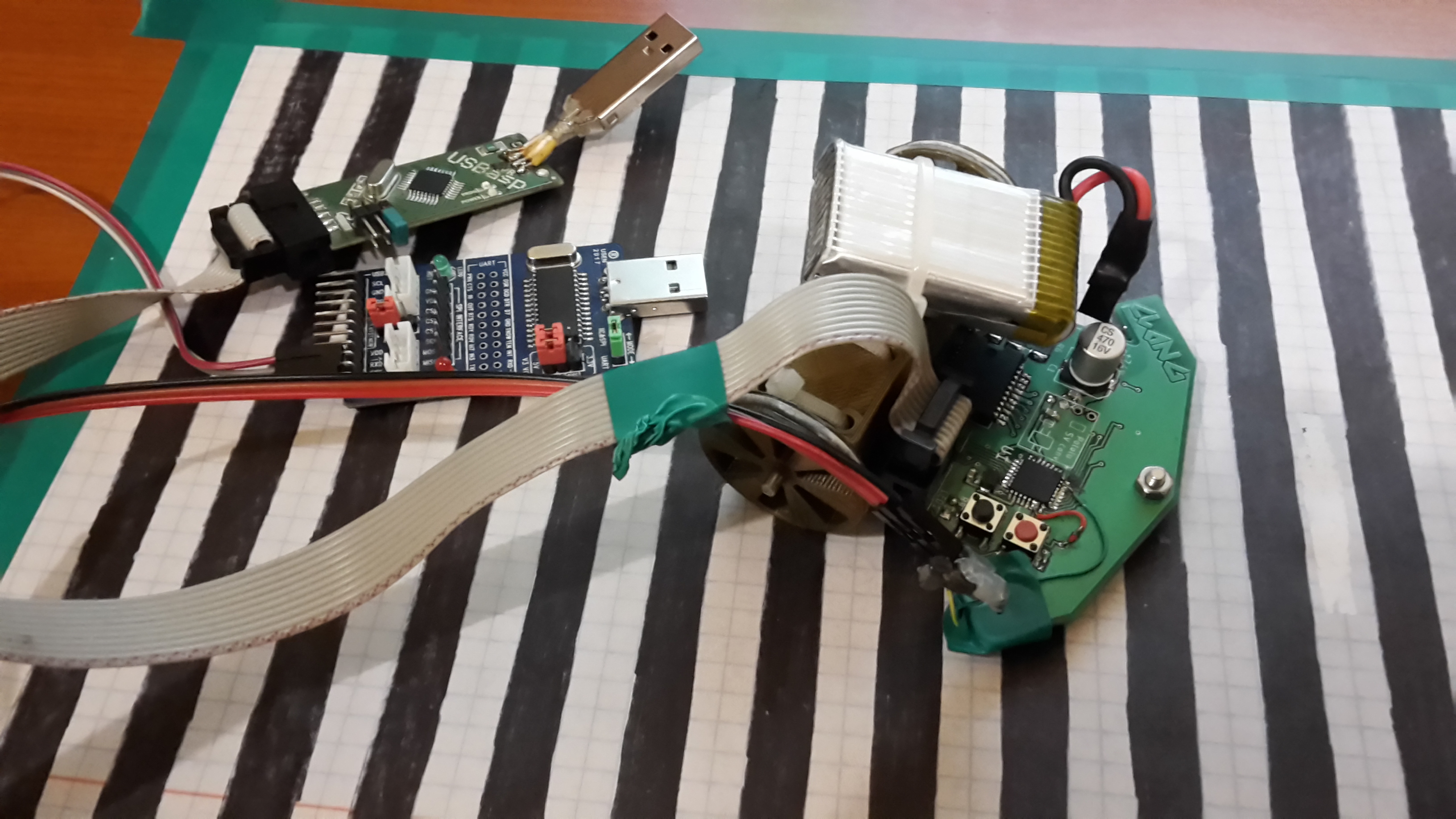
The board is programmed using USBasp programmer. Serial interface is connected to USB-Serial converter for debugging purposes.

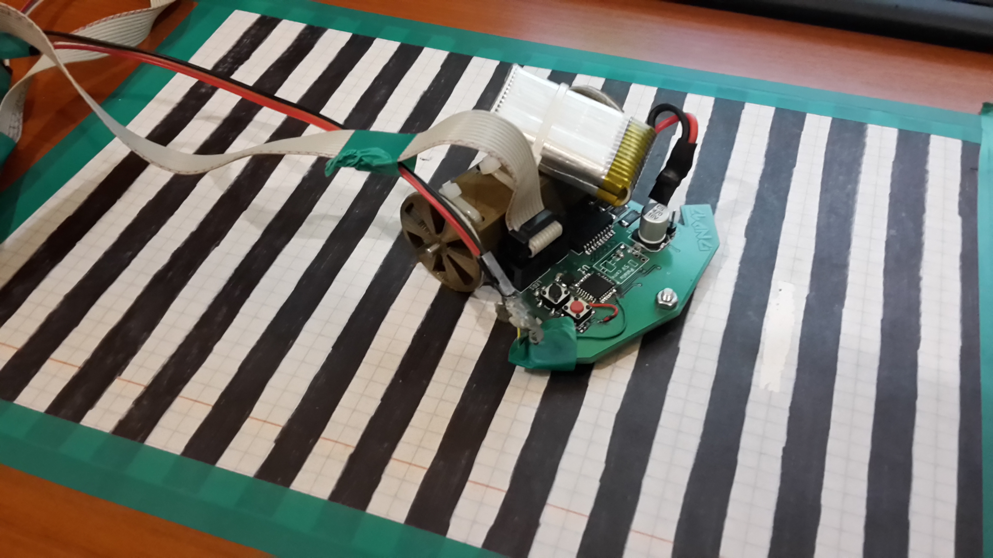
To map motor speed to the voltage applied to them I created this black and white pattern striped track. Width of every stripe is 1 centimeter. This way for each voltage i measured the time between each detected color changes (using one of the two middle sensors). Then from that information, knowing how wide the stripes are I calculated the average speed for a certain voltage.

As you can see here, to properly power the device a small two cell Li-Po battery is needed.
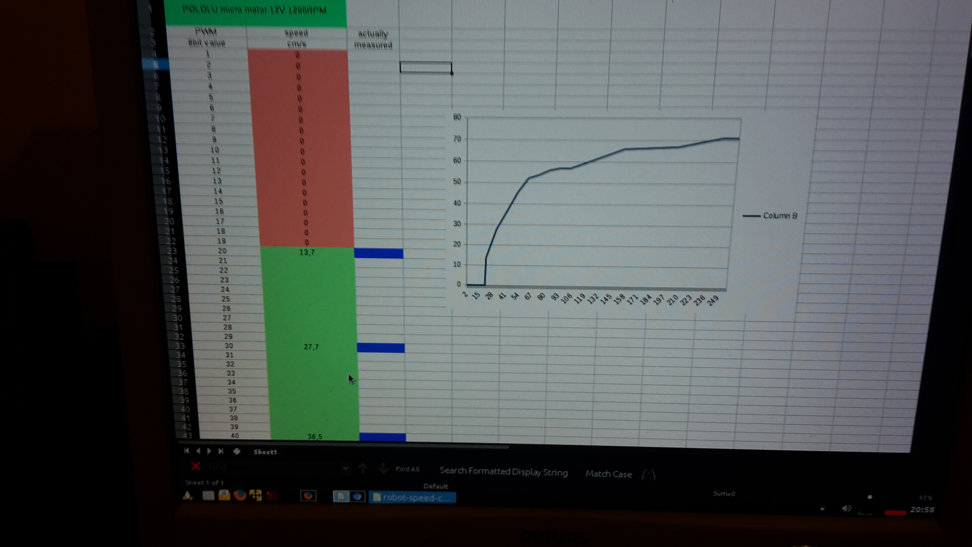
Here's the curve that I got from a series of measurements. This curve was then used to trim the speed that is set in code for both motors that move this robot.
Here's how the whole test and calibration setup looks like:

And here's the video showing how it works:
