… and welcome to my blog. If you find my work interesting check out my github profile as well. Feel free to reach out to me via the email button below.
Fitting a standalone ECU into a Nissan Micra K11
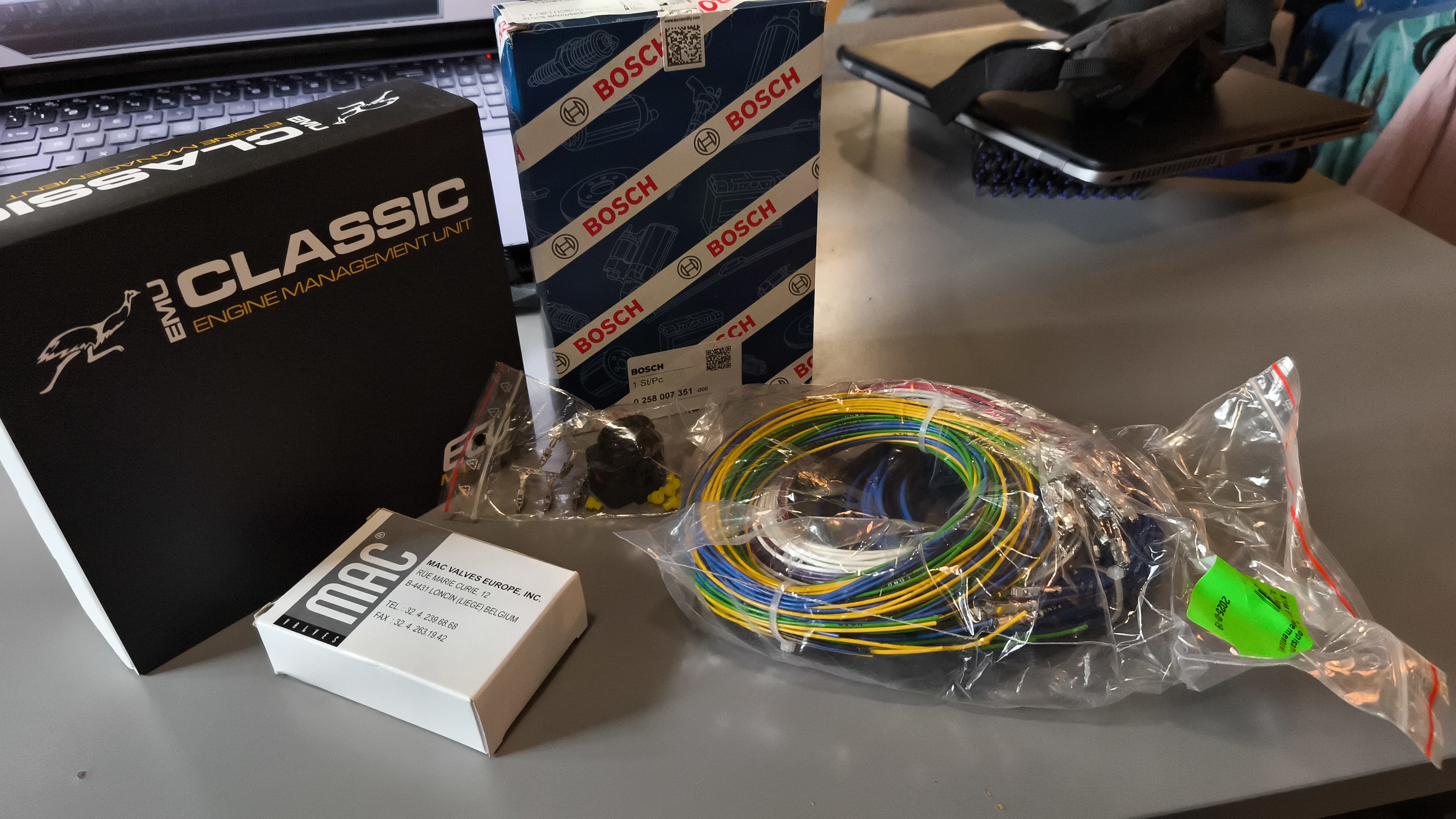
It has been on my mind for a while to learn how to tune a car engine. I own a post-facelift 2000 Nissan Micra K11 that I can experiment on that I can experiment on. So I tried it. I bought ECUmaster EMU Classic set, that contains wires, electronic valve and a Bosch LSU 4.2 Wide Band Oxygen sensor. Since I don’t plan to put a turbo in it, the valve is left unused. Maybe it will be useful to mount nitrous in the future, who knows. I’m all for crazy ideas like that. ...
Label Printer Web Server
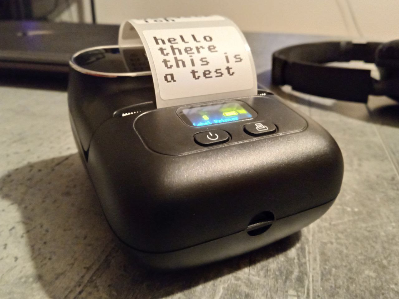
Recently I got a new gadget in my hands, which is a label printer. Very handy device to organize all sorts of stuff at home. But installing a dedicated computer application with custom chinese drivers, just to print a few lines was a bit too much for me. An alternative android app did not satisfy my needs either, it’s bloated with all sorts of options I will hardly ever use. Fortunately, someone already reverse engineered how those printers work and released CUPS plugins. The thing is, release is packaged into an RPM package, which I did not want to bother installing manually on my system (it does not support RPM natively). Not wanting to deep dive into CUPS, I looked for something else. Something dead simple. And I finally stumbled upon this project, which was exactly what I needed. A simple script which takes hardly any arguments, and just prints text. Unfortunately, it did not support my Phomemo printer model, which is M110. I looked at both projects, and derived my own. A simple script that just prints text. If you want to take a look at a script, at the bottom of this post you will find a link to the repository. ...
Cpu Emulator
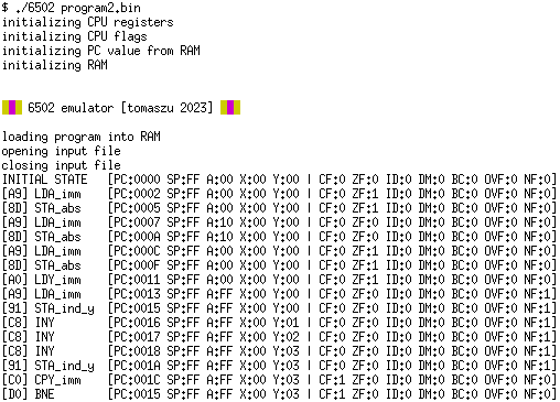
While apparently having too much free time I decided to improve my assembly programming skills. And what would be a better way to prove myself that I can program in a certain language? Write a compiler, of course. Or an assembler in this case. But studying processor instructions one by one is boring, so I had to trick myself into it. I have decided to write my own emulator to fully grasp the idea - become fully aware of what a processor actually does while running. ...
Game Engine
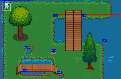
A simple game engine developed on top of Pygame. It supports: simple physics camera management players different types of enemies trapdoor triggers steering live object spawning text boxes buttons … and probably some more. Huge thanks to ciszko for contribution to the project! On top of the engine a simple game was built (main.py, l1.py, l2.py): Game’s name is DING, an onomatopeia for a bouncing object - like a bullet. Basic mechanics is bouncing bullets off of walls to hit enemies. Sometimes you have to do this, because the enemy is completely out of reach. There is no friendly fire at the moment. ...
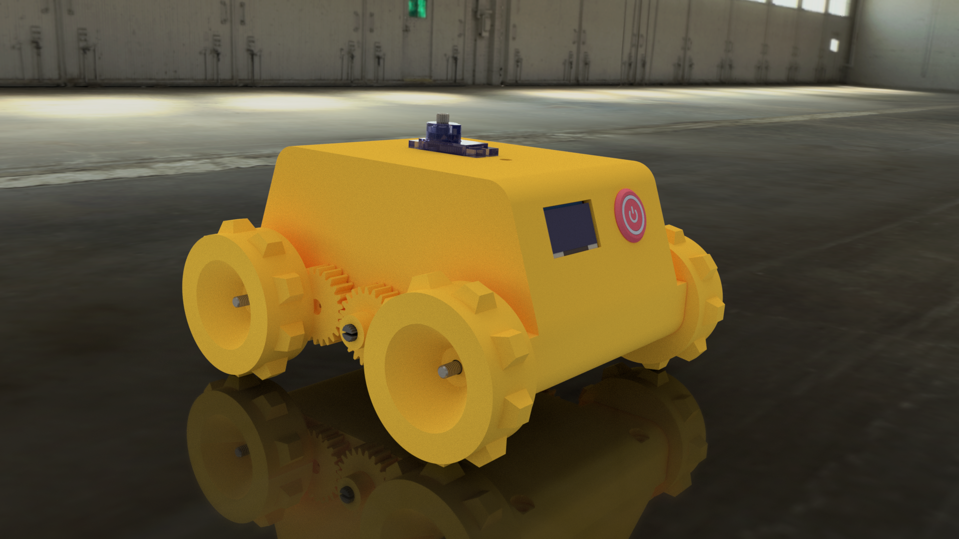
Scanbot
ScanBot is a fully 3D-printed robot equipped with caterpillar tracks capable of dynamically create map of its environment. ScanBot’s ecosystem leverages ROS (Noetic) to gather and process scan data, odometry and to receive steering commands. Low-level it uses a very simple interface which looks like this: <COMMAND>:[PARAMETER1],[PARAMETER2],[...]# Interface is asynchronous and returns data in the same format. Whole system is dockerized. It is also equipped with a Gazebo simulation: ...
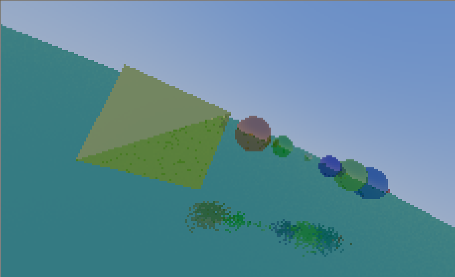
Ray Tracing
I wanted to share a small project that I have created a while ago. It is a simple backwards ray tracer written in C. The scene is defined entirely in C code as an array of structures representing spheres. 3D polygon models can also be loaded from *.obj files. It’s still work in progress and code is a bit messy, but already produces interesting results. ...
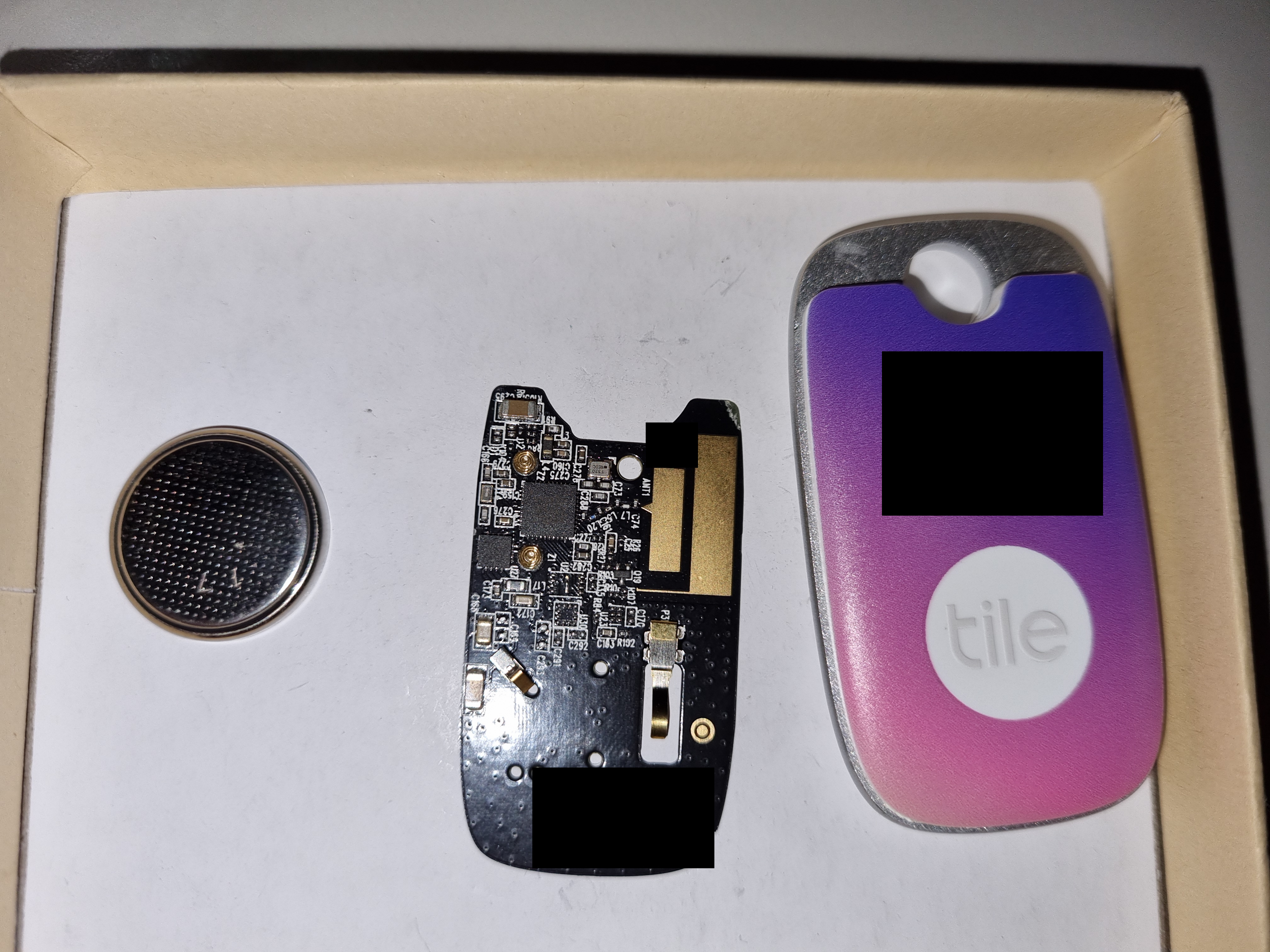
Smart Tag Reverse Engineering
Recently I have received a bluetooth smart tag device. The Apple AirTag kind of thing. It has a dedicated Android and IOs application. No GPS module, yet capable of giving pretty accurate location, and what's more important - playing a nice chiptune enabling you to find your keys/wallet/dog/whatever. You just click a button in your mobile app and it starts its high-fidelity, breathtaking symphony of beeps and boops produced by internal piezo speaker. My first thought (obviously) was how to do something silly with it. And then I found that you can only pick from 10 available ringtones. So there it is. My quest. I need more ringtones. I started surfing the web looking for a solution. I found a single reddit post that gave me some information: Thanks to Reddit user ad2022 ringtone binary format became publicly known. As suggested by monstersgetcreative these songs are signed with a private key, so they cannot be tampered with by others without having a private key to sign a new song. Even if that was true, I could just replace the public key device-side that is used to decrypt a song, and prepare a new ringtone set, signed by me. And maybe it is just a simple CRC that prevents data corruption when uploading new songs. How do I know that ringtones are not just hardcoded and stored on a tag itself? According to reddit post, ingtones can be found in mobile application. Also, when changing it from the app, it takes a while, which suggests that it's uploading it, not just picking a preset. So either way if there is a signature involved or a CRC sum, finally it has to be stored somewhere in tags persistent memory. So I can just look for a ringtone, edit a few bytes and hear a difference. Or is there more to it? First lets examine the hardware. Nice, compact enclosure, pop up plate on the back. One 3V coin cell to power it. Underneath there is a nicely manufactured black PCB. And no screws. Very carefully I pop the enclosure open, making sure it can be reassembled later. One side reveals a button and a bunch of test pads labeled Exx TPxx and a group of test pads labeled J11. Some of these are probably used for programming, right? On this side there are two chips and some external components. And also springs connecting piezo with the board. By looking at traces it seems that the smaller chip has to be the piezo driver. And the big one is labeled NRF52820. It's a Nordic Semiconductor Bluetooth SoC. It's datasheet is publicly available and contains pinout for this package. This chip has SWD (Serial Wire Debug) interface that can be used to program it. Using multimeter set for continuity testing I traced the available test pads to the chip to determine which lead to programming pads. I got almost every pin. SWDCLK - E13 test pad or second top-left on J11 pads SWDIO - directly to mcu (look nrf52 datasheet) GND - J11 test pads top left when looking so that button is above pads 3.3V - J11 pads, top right, button is above pads - vcc SWDIO is not connected to MCU, at least not directly. Either way I couldn't locate a test pad for it. So I soldered a tiny wire directly. Now it's time to read the memory. I wouldn't even start soldering if I didn't have my good old chinese stlink clone laying around: I used OpenOCD to communicate with the chip. Bingo. It listed out all the available flash banks. I halted the chip and dumped all two available banks. One flash bank is 256kB and the other one is 4kB. The bigger one is flash memory that the chip runs code from, the smaller one is used as an EPROM-like persistent storage. Now the fun part. Uploading another ringtone to the device and dumping flash. For diffing I use radiff2 - a part of radare2 suite. There are 6 memory locations (lets call them blocks) that are differrent between dumps. At least one of them has to contain a ringtone. To further inspect I dumped the same firmware twice at different times and see the diff then. After operations described above I could identify proper locations. 1 and 3 - different between dumps with same ringtone, we can rule them out 2 and 4 - identical 3 and 6 - identical 2 and 4 are too short to contain such long ringtones, that can be determined by the number of notes played times 16 bits. Also, 3 and 6 contain very repetitive data which format looks like a ringtone format described on reddit: dump 1: 0x0003e1f0! 4b0352034b0352034b0352034b035203 K.R.K.R.K.R.K.R. 0x0003e200! 4b030007520a4f0a4b0a460a430a460a K...R.O.K.F.C.F. 0x0003e210! 4b0a4d0a4f034b034f034b034f034b03 K.M.O.K.O.K.O.K. 0x0003e220! 4f034b034f034b03000750034d035003 O.K.O.K...P.M.P. 0x0003e230! 4d0350034d0350034d0350034d030007 M.P.M.P.M.P.M... 0x0003e240! 500a4d0a4a0a460a410a460a4a0a4b0a P.M.J.F.A.F.J.K. 0x0003e250! 4d034a034d034a034d034a034d034a03 M.J.M.J.M.J.M.J. 0x0003e260! 4d034a0300074f034b034f034b034f03 M.J...O.K.O.K.O. 0x0003e270! 4b034f034b034f034b0300074f0a4b0a K.O.K.O.K...O.K. dump 2: 0x0003e1f0! 3e043f08420d0004440e000345064206 >.?.B...D...E.B. 0x0003e200! 45064206450642064506420645064206 E.B.E.B.E.B.E.B. 0x0003e210! 45064206450646074207460742074607 E.B.E.F.B.F.B.F. 0x0003e220! 4207460742074607000d3d043e043f09 B.F.B.F...=.>.?. 0x0003e230! 420d0005440e00034506420645064207 B...D...E.B.E.B. 0x0003e240! 45064206450642074506420645064206 E.B.E.B.E.B.E.B. 0x0003e250! 45064607420746074207460742074607 E.F.B.F.B.F.B.F. 0x0003e260! 42074607000d3d043e043f09420d0005 B.F...=.>.?.B... 0x0003e270! 440e00034607490746074b11500c0005 D...F.I.F.K.P... The I patched some data in the block 3 and see what happens. I put single note, described by two bytes (0x5a0a), repeated over most of the song. Nothing happened. The uploaded ringtone still plays. Then I tried block 6. Still nothing - that is expected. Probably these are stored in two memory locations just to be sure data hasn't beed corrupted. The ringtone might be transmitted two times, once per both of these locations, with saved CRC sum or a signature to make sure that it won't arrive broken. But what if we modify both ringtones? Either the tag doesn't play anything or it plays a corrupted ringtone, because it can't play anything else? Well, surprise. It magically played it. Is there a possibility that each time we call it, a ringtone is uploaded again? I deciced to check that theory. Uploading a ringtone Dumping the memory Modifying blocks 3 and 6 Uploading firmware back Calling the tag It played the whole unmodified ringtone. I have dumped the firmware again and ringtone memory blocks were still broken. So we ruled out that by calling the tag we upload a new ringtone and "fix" it. How does the device know what notes to play even though we wiped them? This was the time I gave up the project for a longer while. After a few months i found the strength and patience to try again. Modified block 3 - ringtone plays. Modified block 6 - ringtone plays Modified both blocks - ringtone plays Wait a second. The third one. That's not the ringtone I uploaded... Apparently there is a third, backup ringtone in the memory. It plays when both transmitted ones are broken. I missed it when I tried before, simply because it was the same melody I was modifying and uploading. After further diffing I found that this backup ringtone is also present in two places in the memory - let's say blocks 7 and 8. So one way to make the modified ringtone work is to: Invalidate block 3 Invalidate block 6 Put ringtone in block 7 Put ringtone in block 8 This way I ignore the logic behind blocks 7 and 8, as I put the exact copy in both locations it should just work. And it did! The next step was to prepare a more interesting ringtone: I have created a simple tool that you can use to prepare your own song and upload it. Code is available at this github repository. Please refer to the README file for more information on how to use it. ...
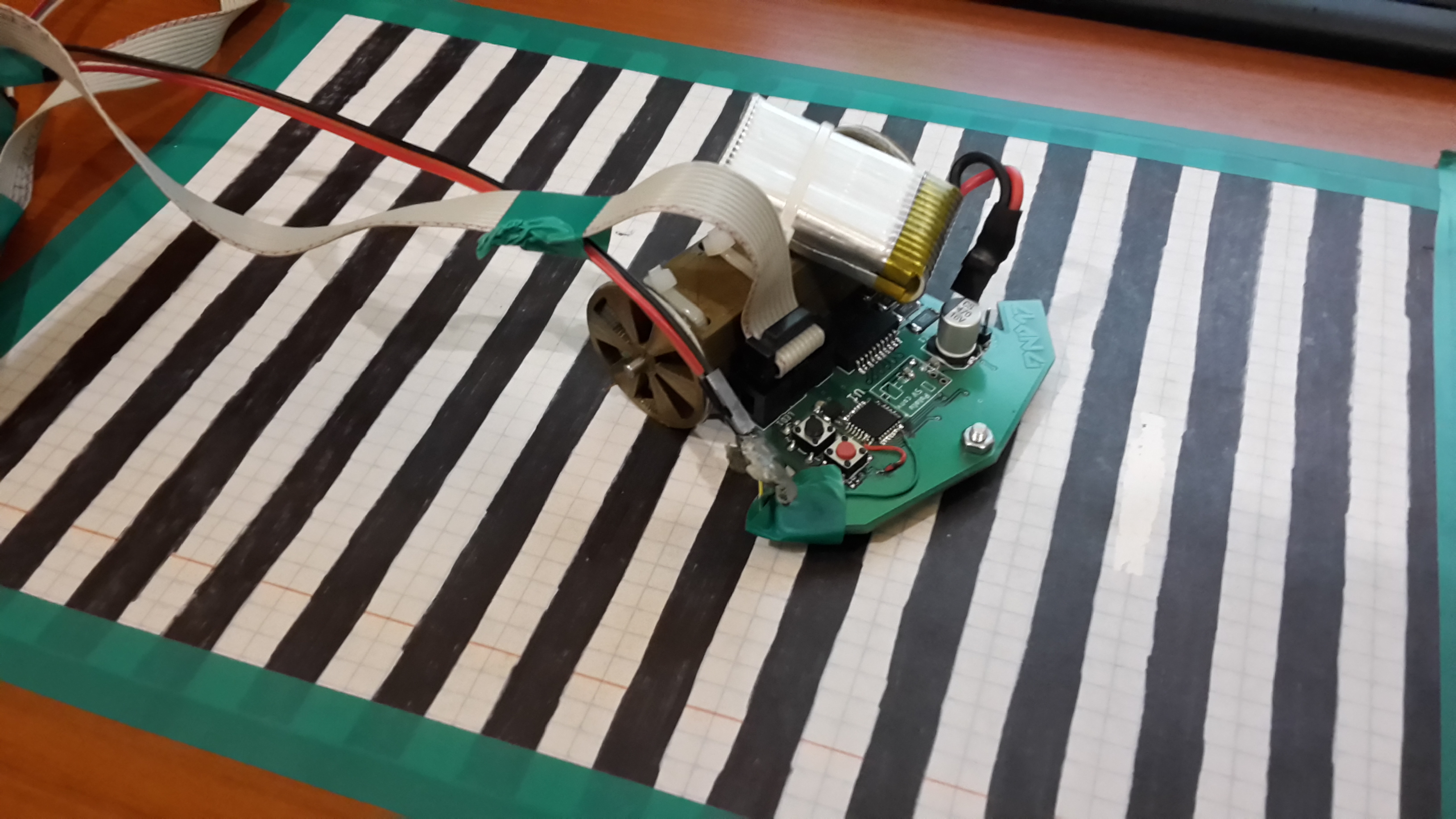
Line Follower
Code, board design and motor mounting bracket 3d design is available at this github repository. The heart of this project is Atmega328, the same microcontroller as used in Arduino Nano. It's programmed using Arduino core libraries. Underneath the robot has six light reflection sensors (optotransistors) that detect brightness of the surface underneath. The board is programmed using USBasp programmer. Serial interface is connected to USB-Serial converter for debugging purposes. To map motor speed to the voltage applied to them I created this black and white pattern striped track. Width of every stripe is 1 centimeter. This way for each voltage i measured the time between each detected color changes (using one of the two middle sensors). Then from that information, knowing how wide the stripes are I calculated the average speed for a certain voltage. As you can see here, to properly power the device a small two cell Li-Po battery is needed. Here's the curve that I got from a series of measurements. This curve was then used to trim the speed that is set in code for both motors that move this robot. Here's how the whole test and calibration setup looks like: And here's the video showing how it works: ...

Maze
The program generates halls of the labyrinth by the use of Depth-First Search (DFS). Below I present a step-by-step explanation of how it works. First, the direction of movement is randomized. Then, the step is made and recorded on a stack. [1] [X] STACK: RIGHT [X] [1] [2] STACK: RIGHT UP This cycle repeats until there is no turn available - then values are taken one by one from the stack and each step is repeated in reverse, e.g. step to the left means we now step to the right. [5] [4] [3] [6] [1] [2] [7] [8] [X] STACK: RIGHT UP LEFT LEFT DOWN DOWN RIGHT RIGHT [5] [4] [3] [6] [1] [2] [X] [#] [#] STACK: RIGHT UP LEFT LEFT DOWN DOWN RIGHT RIGHT Every step back a check is run if any other direction of movement except of the return direction is available. If there is any available, the next step direction is randomized from available directions. Then the first cycle is applied as previously described. For each visited cell that is not on a stack anymore we leave a mark (#) meaning the cell was visited once and should not be revisited.The algorithm finishes when the stack is empty. There is a simplification in the example above. To represent the maze we need data about walls. The solution is simple - make grid bigger and jump two cells at a time. Also mark in-between cells as visited. [5] [#] [4] [#] [3] [#] [#] [6] [1] [#] [2] [#] [X] [#] [#] [#] [#] So this more or less how it works - and now you can try it for yourself. Simply clone the repository from here and build the program. Make sure you have required dependencies (OpenGL, glfw, X11, glad etc. - check Makefile). Camera zoom is adjustable by using Q and E keyboard keys. ...
About Me
I graduated with a BEng degree in ICT at Wrocław University of Science and Technology, following MSc at WWSIS Horyzont. My passion is electronics, programming and tinkering. I like to combine all of my skills to create something new or improve the already existing. At work I am a Software Lead Engineer with years of job related experience and over eight years of personal interest in mentioned areas. My coding skills involve mostly C, C++, Python, HTML/CSS/JS, SQL and shell scripting. I have experience with microcontroller programming for platforms like Arduino, AVR ATmega/ATtiny, STM32, ST7, PIC. I speak Polish and English and learn Japanese in a course that I attend. My interest span across everything that moves and contains electronic and/or mechanical components. ...